
Goal: Measure the distance travelled by a single wheel over time
Unless you’re building a unicycle, measuring the distance travelled by a single wheel seems like a fairly pointless exercise. However, bear with me, because with the wonders of ancient mathematics, kinematics and some (fairly broad) assumptions, this is a fundamental stepping stone to building a robot that can determine its relative position from a known origin using dead reckoning.
At this stage it was time to upgrade from my rickety little “wheels attached to battery case” rig onto a more sturdy platform, so I put in another order with robotgear.com.au:
- Pololu 5″ Robot Chassis ($18.90)
- Pololu 42x19mm wheel & encoder set ($45.95)
After a bit of stuffing around tuning up the encoder to work at 3.3V and get the pulse trains back in the right phasing (instructions here at Pololu) I was ready to go.
Muuuuuuuum! Are we there yet?
Just as your car’s odometer measures the distance you’ve travelled on your summer holiday, odometry for robotics does the same: it’s purpose is to use sensor data to determine distance travelled by the robot over time. By combining this information with the physical attributes of the robot itself, relative position can be reckoned (but more on this to come).
A common method of odometry is to measure how many rotations (or partial rotations) a wheel has made. You may have actually done this yourself as a kid: did you ever have to walk around the basketball court at school with a little wheel on the end of a stick? If so, you’ve been a human odometer. If we know the circumference c of the wheel is 1m and the wheel rotates once, then we must have travelled 1m (caveat: this ignores any slippage, which turns out to be a significant problem with wheel-based odometry). Furthermore, as the first derivative (with respect to time) of position is velocity, we can say that if the wheel rotated once in 1 second, it must be rotating at 1m/s (3.6km/h).
Rotary Encoders
 So far, so good. But how can we put this into practice with the wheel(s) of a robot? A common option is to use a rotary encoder such as the Pololu encoder I have used here. This is an optical encoder and uses two infrared reflectance sensors that shine infrared light onto the inside of the wheel hub, upon which is arranged 12 “teeth” with gaps between them.
As the wheel rotates around the shaft of the motor, the teeth pass over the reflectance sensors. When a tooth is above a sensor it reflects infrared light and when no tooth is above it doesn’t. The sensor (after some signal cleaning) outputs a pulse train: high, low, high, low that corresponds to tooth, no tooth, tooth, no tooth. The higher the frequency of the pulse train, the faster the wheel is turning.
A single sensor is good: its pulse train allows us to determine how fast the wheel is rotating, but it lacks a critical bit of information: in which direction is the wheel rotating?
This is where the second sensor comes in. The sensors are physically positioned to provide the same pulse train, but 90 degrees out of phase with one another: a quadrature output signal. When the wheel is rotating in direction A (ie. clockwise) the pulse train from sensor A “leads” that of sensor B (because the tooth passes over A first) and when the wheel is rotating in the opposite direction (ie. counter-clockwise) the pulse train from sensor B “leads” that of sensor A (because the tooth passes over sensor B first).
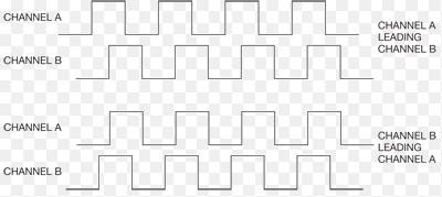
Image Courtesy of EDN
Looking at the quadrature output when sensor A leads sensor B (the top two pulse trains, let’s assume this represents clockwise rotation), it can be seen that for a series of consecutive rising and falling edges, the state of the outputs forms the following state table:
| Sensor A | Sensor B |
|---|---|
| 1 | 0 |
| 1 | 1 |
| 0 | 1 |
| 0 | 0 |
Also note that this pattern is cyclical. Once the final state is reached, it will wrap around to the first stage again.
Looking at the quadrature output when sensor B leads sensor A (the lower two pulse trains, let’s assume this is counter-clockwise rotation), it can be seen that for a series of consecutive rising and falling edges, the state of the output forms the following state table:
| Sensor A | Sensor B |
|---|---|
| 0 | 1 |
| 1 | 1 |
| 1 | 0 |
| 0 | 0 |
Notice that the second is exactly the same state table as the first, just “starting” on a different state and transitioning backwards? If so, please collect the big fluffy bear as your prize. The transitions are exactly the same, they just occur in the… opposite direction (because the wheel is rotating in the opposite direction).
Side note: this state table is a gray code, the hamming distance between adjacent states is always 1: only one of the two outputs ever changes its level between adjacent states. If we ever see both outputs change state at the same time then we know there has been an error: there is either noise corrupting the signal or we missed a transition (this latter part is important later on as we’ll be measuring these transitions using interrupts, which, depending on our hardware, could be missed).
To summarise:
- Our encoder uses an infrared sensor to detect wheel rotation by measuring reflected light bouncing off teeth in the wheel hub
- The sensor outputs a pulse train that indicates when a tooth is present / not present
- By counting the pulses we know how many teeth have passed by the sensor
- By knowing the circumference of the wheel and the number of teeth we can determine the distance the wheel has rotated
- By measuring the time it took for N teeth to pass, we can determine the velocity of the wheel’s rotation
- By adding a second sensor, positioned next to the first, we get two identical pulse trains, 90 degrees of out phase with one another
- Because a tooth must pass over one of the sensors “first”, we can determine the direction of rotation by examining the phasing of the pulse trains
So, if we can get the Beaglebone Black to monitor these pulse trains, we can work out how the wheel is rotating (and as we have two wheels, we’ll end up with two of everything: two encoders, two sets of pulse trains, four individual signals to monitor).
Detecting Interrupts with Beaglebone Black’s GPIOs
As well as the many peripherals (PWMs, ADCs) that can be exposed on the Beaglebone’s external pins, most of them can also act as General Purpose I/Os (GPIOs), capable of acting as inputs (which determine the level of the signal applied to them) or outputs (which generate a signal, ie. to drive an LED or other external device). When configured as inputs they can also generate interrupts on a rising of falling edge of the input signal and this is the functionality that I used to monitor the encoder signals and thus implement the odometer.
Unfortunately, when I was working with the Beaglebone Black it was still quite fiddly to configure the GPIOs. Recall from earlier posts that the BBB has a lot of internal peripherals whose functionality is multiplexed out onto external pins according to the device tree. In order to change what gets mapped onto which pins, device tree overlays are used to reconfigure the hardware at runtime. So I had to write a DTO (Device Tree Overlay) that configured P9_11, P9_13 and P8_7, P8_8 (there is nothing magical about this choice of pins other than that they can act as GPIOs and aren’t being used for the PWM or ADC in this project) as GPIOs in input mode and load this before running my odometer program. Derek Molloy has a great tutorial about using the GPIOs on the BBB and writing / compiling DTOs here. You’ll want to read it if you haven’t before.
Putting this all together, to implement the odometry I had to:
- Connect the two outputs from each rotary encoder (one per wheel) to external pins on the BeagleBone Black that can act as GPIOs (P9_11, P9_13, P8_7 and P8_8 in my case, these are protected with 100ohm inline resistors)
- Write and compile a Device Tree Overlay that multiplexes the external pins to GPIOs and configures their hardware as inputs
- Write some code that uses the virtual files in sysfs to export control of the GPIOs into userland (a directory of virtual control files is created for each GPIO that is exported, Derek’s tutorial discusses this in detail) and then configure the GPIOs as inputs that generate interrupts on both rising and falling edges
- Write some code that monitors the state of the encoder outputs by waiting for interrupts on the GPIOs and measures the direction and amount of rotation
The code itself is on github and documented, but I wanted to explain in some more detail how the main odometer loop works and the assumptions that it makes. The code performs odometry for two encoders/wheels, but to simplify the explanation below we assume we’re dealing with just one encoder.
- It tracks five values for each encoder (wheel):
- The current state (as measured directly after the interrupt, or assumed based on logic) of each sensor (currentA and currentB)
- Assumed based on logic is… an assumption. If we trust that the phase difference between the two pulse trains is always 90 degrees, that it is only possible for the states to transition between adjacent codes according to the gray code and that we do not miss any interrupts then when an interrupt (rising or falling edge) occurs on one sensor, if we measure the level of that signal we can assume we know the level of the other sensor – because it follows a gray code it cannot have changed since the last interrupt (because only one signal can change a time between adjacent gray code states, and the changing signal must have been the one experiencing the interrupt). This assumption falls apart if we miss an interrupt for any reason (ie. the processor was busy, something got lost in noise etc). In that case, we may not actually be in the state immediately adjacent to the last one we measured: we could be several/hundred/millions of states further on.
- The previous state (at the last interrupt) of each sensor (lastA and lastB)
- A counter that increments by one for each forward transition (“tick“) and decrements by one for each backward transition (“tick“) through the state table (odometer).
- If odometer == 0 and then the wheel rotates forward/clockwise over the course of five consecutive interrupts/ticks, odometer == 5.
- The Pololu encoder generates 48 ticks per complete revolution of the wheel. Thus, if the wheel has a radius r = 2cm and thus a circumference c = 12.57cm, if we see 48 consecutive transitions through the table in a single direction, the wheel has turned 12.57cm. If we see 24 consecutive transitions through the table in one direction, and then 24 consecutive transitions through the table in the opposite direction, the wheel has still turned 12.57cm, but if it were travelling in a straightline over ground it would be back at its origin position.
- The current state (as measured directly after the interrupt, or assumed based on logic) of each sensor (currentA and currentB)
- Before looping, it opens 2 file handles, one to each GPIO (we need 2 GPIOs per rotary encoder, one to measure each pulse train)
- The main loop construct is built around a blocking poll() on the file handles. An interrupt on either of the GPIOs (ie. the detection of a rising or falling edge on one of the encoder output pulse trains) causes the poll to return.
- It then determines which GPIO had the interrupt and reads the state of that GPIO (ie. the current level of the pulse that just experienced the edge). Going back to the assumptions above, it now “knows” the current level of both sensors: currentA and currentB.
- It XORs the current level of each sensor against the level of the opposite sensor at the last interrupt (lastA and lastB) which allows it to determine whether it is transitioning “forward” or “backward” through the state table, and thus the direction in which the wheel is rotating. The odometer counter is incremented or decremented accordingly. It also performs a basic sanity check to ensure the current states do not violate the gray code (which probably indicates that we’ve missed an interrupt and cannot be certain of our count any more).
To illustrate, we can walk through several ticks from a reset state and see what happens. To refresh, the gray code for the encoder is:
| State | Sensor A | Sensor B |
|---|---|---|
| 0 | 0 | 0 |
| 1 | 0 | 1 |
| 2 | 1 | 1 |
| 3 | 1 | 0 |
tick 0 (power on)
Note: This assumes the initial state of the encoder is 0 (ie. sensor A = 0, sensor B = 0). If it’s not we just get an initial gray code violation error, the code could be made more robust by simply measuring the actual starting state).
currentA = 0
currentB = 0
lastA = 0
lastB = 0
odometer = 0
tick 1 (first interrupt, rising edge on B: state 0 -> state 1)
currentA == 0 (this is assumed, because interrupt occurred on b)
currentB == 1 (this is read now, because interrupt occurred on b)
lastA == 0
lastB == 0

if (currentA ^ lastB) odometer--;   // false
if (currentB ^ lastA) odometer++;   // true

NOTE: The above determines whether the transition is from state 0 to state 1 (forwards) or from state 2 to state 1 (backwards). If lastA
and lastB had been 1 (ie. previous state was state 2) the odometer would have been decremented.

lastA = currentA = 0
lastB = currentB = 1
odometer == 1
tick 2 (second interrupt, rising edge on A: state1 -> state 2)
currentA == 1 (this is read now, because interrupt occurred on a)
currentB == 1 (this is assumed, because interrupt occurred on a)
lastA == 0
lastB == 1

if (currentA ^ lastB) odometer--;   // false
if (currentB ^ lastA) odometer++;   // true

lastA = currentA = 1
lastB = currentB = 1
odometer == 2
tick 3 (third interrupt, falling edge on B: state 2 -> state 3)
currentA == 1 (this is assumed, because interrupt occurred on B)
currentB == 0 (this is read now, because interrupt occurred on B)
lastA == 1
lastB == 1

if (currentA ^ lastB) odometer--;   // false
if (currentB ^ lastA) odometer++;   // true

lastA = currentA = 1
lastB = currentB = 0
odometer == 3
tick 4 (fourth interrupt, direction reversed, rising edge on B: state 3 -> state 2)
currentA == 1 (this is assumed, because interrupt occurred on B)
currentB == 1 (this is read now, because interrupt occurred on B)
lastA = 1
lastB = 0

if (currentA ^ lastB) odometer--;   // true
if (currentB ^ lastA) odometer++;   // false

lastA = currentA = 1
lastB = currentB = 1
odometer == 2
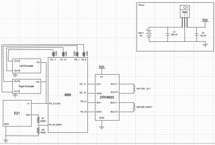


Hello, Could you say which software you used to make the schematic diagram showing the circuit connections? Thanks, /Sagar
Hi Sagar. Those diagrams are made using Omnigraffle for Mac. It’s definitely not the most appropriate tool for the job, it’s just what I had with me when I wrote that post. Take a look at TinyCAD.
Thanks. I will check out TinyCAD.
I may have not seen it, but i can’t find any such thing in your github repository close to a kernel module for the sysf.
Have they disappeared ?
Hi there, the interaction with the various kernel modules is via sysfs (ie. it’s via files exported by the BBB kernel modules into userland).
I could take 1200 ticks per complete revolution of the wheel with this encoder:
https://www.pololu.com/product/2598
thanks to to measure is taken before the gearbox ratio (1:100)
Thank you for sharing 🙂