
Goal: Get the robot to drive around the room and avoid obstacles
Once the DRV8833 was hooked up to the two DC micro motors and the BBB’s PWMs, I wrote some simple C++ code to abstract movement (ie. forward(), reverse(), spinLeft(), spinRight() etc). It was now possible to write little programs to move around along a predetermined path. At this point the robot had no idea where it was, but was capable of driving forward for 2 seconds, turning left, doing that some more and making a square for example.
It’s worth noting at this point that although I later took some actual measurements as to the mechanical differences between the two motors and how they each uniquely responded to the same PWM duty cycle, during this early phase a DC of 50% more than adequately drove the robot in a “straight” line for small distances (and it was obvious from trial and error that there was a critical minimum DC at which the motors did not generate enough torque to turn the wheels when in contact with the floor).
Before I delved further into location awareness and odometry, I wanted to test out the Maxbotix MaxSonar-EZ1 ultrasonic transducer that I had bought and get some practice with the BeagleBone’s built-in ADC. The aim was to write a simple finite state machine to:
- Drive forward while measuring proximity of objects in front of robot using the ultrasonic transducer
- When a “safe” distance threshold was breached, slow down
- When a “danger” distance threshold was breached, enact collision avoidance (ie. reverse a bit, spin around, drive forward again)
With the PWMs and DRV8833 all the driving component was taken care of, the major work was in interfacing with the MaxSonar-EZ1.
MaxSonar-EZ1
For hobby work this is one of the kings of ultrasonic sensing (and the price tag reflects it!). In the past I’ve worked with bare 40kHz transducers and built 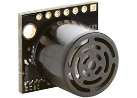 an amplifier and wave generator for them, along with interfacing them back into timers for distance measurement, but a package like the EZ1 takes care of all of this for you.
The EZ1 has a typical 30cm deadzone, but outside of that has excellent resolution (they claim 1mm), a 5m range (I’ve only tested it up to about 3m in my apartment, but it gives linear readings all the way out to that distance) and supports multiple interfaces including analog voltage output (although this decreases the object detection resolution to 5mm), serial over TTL, serial over RS232 and PWM.
I really haven’t explored all the options this thing has to offer because it was so simple to get up and running, but with the other output options and the ability to start and stop its sensing, it can be used a lot more effectively than I’m currently using it here. The datasheet is easy reading and the Quick Start Guide is useful for playing around with it on the bench.
Using the BBB ADC
The MaxSonar-EZ1 supports multiple output methods but for my testing I wanted to use the analog output so I could play around with the BBB’s ADC. The EZ1 can run on anything from 2.5V – 5.5V DC and the analog output voltage it emits to represent distance obviously scales within 0V and the nominated supply voltage. In my case I am powering it from the 3.3V output on the BBB itself (available on pin 3 of the P9 header).
The BBB has a 7 channel ADC with 12-bit resolution. The most important thing to note is that the ADC inputs are 1.8V logic: do not exceed this or you’ll fry it. Because we’re supplying the EZ1 with 3.3V, its analog output (on pin 5 of the EZ1 board) must be put through a voltage divider so the BBB ADC only sees up to 1.8V.
I’m using a simple 50/50 divider built from two 200ohm 0.1% error tolerance resistors, the output of the voltage divider is being fed into pin 33 on P9, which corresponds to AIN4 (the 5th ADC input). It’s important to use low error tolerance resistors because we’re trying to measure a voltage that varies between 0 – 1.8V with a 12-bit resolution (4096 possible values). Technically this gives the ADC the ability to differentiate down to the sub-mV level (ie. one quantisation step represents around 0.44mV: if the resistors skew the real output from the EZ1 then you can lose noticeable accuracy.
The ADC also needs a GND reference connected (pin 34 of the P9 header), I simply connect this to pin 2 of the P9 header which is connected to the BBB ground.
Like with the PWM, on the version of Angstrom that my BBB came with there is a handy module that exposes the readings from the ADC into userland virtual files, called cape-bone-iio. To enable the ADCs the virtual cape itself must first be loaded (as per the PWM the # in the capemgr directory represents a BBB-specific value, your mileage may vary):
# echo cape-bone-iio > /sys/devices/bone_capemgr.#/slots
Each ADC now has its own virtual file that can be read which will return a value between 0 and 1800: the module takes care of converting the 12-bit resolution into an actual mV reading. You’ll see the OCP reference around quite a bit, I believe it stands for “On Chip Peripherals” – all the good stuff that’s baked directly into the AM3359 processor.
# cat /sys/devices/ocp.#/helper.#/AIN4
2049
The MaxSonar-EZ1’s output voltage can be converted into distance using the formula:
Vcc / 512 = mV_per_inch
distance_inches = mv_from_ADC / mv_per_inch
Because I like working in centimeters and the voltage scale the BBB ADC sees is half that of the actual EZ1 Vcc (because of the voltage divider):
distance_cm = (mv_from_ADC * 512 * 2.54) / 1800
Finally, the readings you get from the ADC might bounce around a bit (ie. try putting something solid a fixed distance in front of the uS sensor and then reading the ADC 5 times in a row, once per second). To get around this I sample the ADC several times (32) with a fixed delay between each sample (1ms: the ADC has a sample time of 125nS so this is plenty enough), then I order the samples and select the median. This is a really inefficient way of doing median filtering, there is a paper about much better alternatives here.
Hipster Circuits, the builders of the incredibly cool Replicape 3D printer cape for Beaglebone, note on their BBB ADC post that newer kernels have changed the way that the ADC is accessed and that cape-bone-iio no longer is used.
Circuit Diagram

