My first goal was to get the Beaglebone using the DRV8833 to drive the two micro motors forward: that seemed like an achievable start (if that wasn’t possible this was going to be a pretty short-lived hobby). It should be easy right? Build a little platform, attach the wheels, apply some voltage, watch it go.
No shell for you. One Year. SSH Host Key Corruption
Early attempts at this were thwarted by the fact I couldn’t SSH into my BBB. The Beaglebone runs an SSH daemon called Dropbear and on first boot Dropbear creates the board’s public/private keypair. If this fails (ie. you accidentally power the board off halfway through writing the files to the BBB’s flash) then you can’t SSH into the BBB. I suspect that this could be happening during factory testing rather than the end user’s first boot: the board is powered on long enough to check for basic operation, but then yanked off the production line and boxed. Other people have experienced this issue and there are some proposed solutions floating around but in the long run I just booted up a second BBB I had and used that: I’m still getting around to reflashing the old one.
BeagleBone Black Pulse Width Modulation
Once I had a functioning BBB the first order of business was interfacing it with the DRV8833. This is an awesome little chip from Texas Instruments that packs two H-bridges capable of driving up to 1.2A each into a tiny space: the last time I built an H-bridge it was about the size of a stamp, these are smaller than a fingernail. The Pololu carrier neatly exposes the chip’s pins and adds some additional components required for its basic operation.
The DRV8833 doesn’t need much to work: simply supply DC power (anything from 2.7V – 10.8V) on one side for the motors and four control signals on the other (the input pins are 3V and 5V compatible, which is great, because the BBB has 3.3V I/O). Each motor (called A and B) has two control signals (AIN1/AIN2 and BIN1/BIN2). Applying a HIGH signal to AIN1 makes motor A spin forwards, applying it to AIN2 makes it spin backwards and so on. See the datasheet for the gory details.
Once the motors are connected and some power applied, a simple test at this point is applying a HIGH signal to the each of the input pins (they’re internally pulled low) and checking that the motors spin in the desired direction. For the robot however, we need more control. We have the need for (variable) speed. Enter Pulse Width Modulation.
When applying a constant signal to xIN1 or xIN2 on the DRV8833 you’re telling the H-Bridge to  supply steady current to the motor (in one of two polarities depending on which control signal is HIGH). This drives the motor at whatever speed it will run for the given input voltage, full speed ahead.
In order to vary the speed we can pulse width modulate the control signal to the motor. A pulse width modulated signal has a specific frequency but a varying duty cycle. That is to say that the rising edges of each cycle occur the same wavelength apart (constant frequency) but the duration of the cycle where the signal is HIGH vary: we are modulating the width of the pulse. The longer that each pulse stays HIGH for, the more time the DRV8833 will deliver voltage/current to the motor and the faster it will run.
If your embedded device has any form of digital I/O then it’s possible to write your own PWM routine in software (assuming you have a reasonably stable clock source/timing) but luckily for us, the BBB has a heap of onboard peripherals, including the “Enhanced High Resolution Pulse Width Modulator” (eHRPWM).
We can use this to PWM the control signal to DRV8833’s input pins and control the motor speed. If we apply our control signal to AIN1 we can vary the forward speed of motor A, if we apply it to AIN2 we can vary the reverse speed of motor A.
Device Tree
Before delving into how the eHRPWM can be used however, a brief historical tour of the entire known universe must be undertaken to understand why Device Tree and Device Tree Overlays exist and why they are important when it comes to PWM (and almost any other hardware) on the BBB.
- Linus Torvalds starts writing Linux in 1991, initially the kernel is very x86-centric
- Linux kernel is ported to a few other CPU architectures such as Alpha and SPARC around 1995
- Linux begins being touted as a serious alternative to commercial UNIXes and desktop platforms around 1998-2000
- Custom machines/boards built on SoC concepts increase exponentially, people start porting Linux kernel to an increasing number of hardware platforms
- Kernel requires lots of board-specific code to describe the specific hardware on a board, many boards need their own kernel image
- Everyone gets sick of having to manage so many board-specific differences being introduced into the kernel
- Linux kernel introduces support for Device Tree, a data structure that describes the hardware in a system (ie. where to find it, how to interface with it) to the kernel
x86 PCs have been around a long time and despite supporting hardware and software from a huge variety of sources, at their heart there is a lot of standardisation other than just the x86 instruction set. One area of (relative) standardisation is the BIOS and concepts such as ACPI which allow the kernel to learn about and interface with the underlying hardware (ie. decode keystrokes from a keyboard, write a character to a display, discover devices on a bus etc). One of the kernel’s first tasks as it boots the machine is to discover and configure the hardware: how many CPUs are available? How much RAM is there? What peripheral devices are available that it may have device drivers for?
The BIOS and things like ACPI are used to do this on IBM PCs but for custom boards using SoCs which may contain many custom peripherals, there isn’t necessarily a lot of standardisation. One board might have a PWM, one might have some GPIOs, many have both, but almost all of them expose the registers, memory mappings and control interfaces to these devices in different ways. Before Device Tree, custom code had to be written to describe a SoC implementation to the kernel and this was generally compiled into the kernel image itself.
Device Tree provides a standard data structure to describe system hardware to the kernel and better yet, allows this data structure to be passed to the kernel at boot time, rather than compiled into the kernel image. Now it is possible to have one kernel image that via DT support and kernel modules can support many different board configurations, much as many Linux-on-PC users enjoy. You can learn more (yay!) about the rationale behind Device Tree here and here.
Device Tree Overlays and BeagleBone Capes
Device Tree support helped clean up the kernel for SoC board developers, but hardware like the Beaglebone Black takes the requirements one step further.
Although there are many useful peripherals on the BBB, one of its major features is its extensibility via capes, which are hardware boards that fit over the top of the BBB (like a… cape… on a Beagle). A user plugs a cape (or many, they’re stackable) onto the BBB and when the board boots the kernel magically discovers the cape, configures its hardware (ie. an LCD screen) and makes it available to the rest of the OS. (By magically I mean the BBB reads an EEPROM on the cape that describes the cape and then loads the right Device Tree Overlay into the kernel to configure the hardware).
Hang on. Device Tree Overlay? “We have to learn MORE to get the motors running?” I hear you say. Just a little. Look, it’s not much more, the scroller is almost half-way down the page already. A Device Tree Overlay is a fragment of a complete device tree that can be loaded at runtime, after boot. It allows the basic hardware definition (the BBB’s hardware) to be extended (by that of the cape). The Capemgr is some kernel code that was created to allow the right overlay to be dynamically loaded (from disk/flash) based on the capes that are installed.
- BBB boots, kernel uses BBB device tree to find all the BBB’s on-board hardware and configure it
- BBB probes for EEPROMs on any expansion capes accessible via the P8/P9 expansion headers
- Based on data in EEPROM, Capemgr loads the correct DTO to further configure the hardware
It’s sort of like a device driver, or a companion to a device driver if you will: it describes the hardware that a device driver will ultimately control, and like a device driver, it can be loaded dynamically when it’s needed.
BeagleBone Black Built-In Hardware and Virtual Capes
While expansion capes provide some cool extra functionality, the BBB has a heap of onboard hardware (Ethernet, HDMI etc) with a lot of it built directly into the XAM3359 ARM processor. The System Reference Manual is a good place to start to fully understand the capabilities available – pg 53 has a good block diagram of the processor’s features. You probably want to steer clear of the actual AM3359 Technical Reference Manual for the time being: it’s over 4,000 pages – probably not bad if you’re suffering insomnia though.
The problem is that it has so many internal peripherals that there aren’t enough pins on the SOC package, let alone expansion header pins (the BBB has two expansion headers, P8 and P9), to give each one a unique physical interface. For example, pin 21 on the P9 header can be used as a GPIO, a PWM output, for the I2C bus, SPI bus, a UART and more, but obviously not all at the same time.
The processor internally multiplexes the functionality of its various peripherals onto its external pins (many of which are then routed onto the BBB’s P8 and P9 expansion headers for end-user consumption). When we want to use a peripheral (ie. the PWM) we use the Capemgr to load a Device Tree Overlay (DTO) that tells the kernel (and ultimately the processor) to configure the peripheral and also the multiplexer so that the peripheral becomes available on the relevant pin.
There are quite a few DTOs that ship with the default Angstrom Linux distribution on the BBB that configure and expose important peripherals and functions such as HDMI output, the PWM and ADC onto various P8/P9 pins. These are sometimes known as virtual capes: they’re not physical capes that extend the BBB, but virtual ones that reconfigure the on-board hardware in a useful way.
At this stage (in fact, well before now) it’s worth pointing out one of the most useful Beaglebone resources around, the blog and videos of Dr Derek Molloy, Senior Lecturer in the School of Electronic Engineering at Dublin City University. On his pages you’ll find many really informative videos about using the BBB and he maintains two important PDFs: a map of P8 expansion header pin modes and a map of P9 expansion header pin modes. These PDFs can be used to write your own DTOs that configure the BBB’s processor to multiplex the functionality you need out to the right pins. We’ll be doing this a bit later on…
Using the BBB eHDPWM
Luckily, with the version of Angstrom that ships with the BBB (at the moment) you won’t need to write or compile a thing, you can do everything from user-space. There is already a handy kernel module and DTO that allows you to easily interface with the PWMs.
Further information is available here, but to summarise:
- Tell Capemgr to load the AM33xx PWM DTO (this enables the PWMs). The Capemgr is interfaced with via reading and writing to the slots virtual file, the exact directory will change depending on your Beaglebone, the # in mine is 9.
# echo am33xx_pwm > /sys/devices/bone_capemgr.#/slots
- Expose a PWM to a specific expansion header pin. In the example below pin 13 on the P8 header will become a PWM output. From Derek Molloy’s PDFs we can see that P8_13 could also be configured as a GPIO: instead, we’re using it as a PWM.
# echo bone_pwm_P8_13 > /sys/devices/bone_capemgr.#/slots
- Configure the PWM’s frequency, polarity and duty cycle. The # represents a number that can vary between BBBs (but not, for me, between boots, thankfully). The period and duty are specified in nanoseconds. In the example below 500000ns represents a frequency of 2kHZ and the 250000 gives us a 50% DC. Advice varies on the frequency you should use for motor PWM, this works for me, some people suggest 20kHz upwards.
# echo 500000 > /sys/devices/ocp.#/pwm_test_P8_13.#/period
# echo 250000 > /sys/devices/ocp.#/pwm_test_P8_13.#/duty
# echo 0 > /sys/devices/ocp.#/pwm_test_P8_13.#/polarity
- Connect the expansion header pin (pin 13 on P8 in the above examples) to the DRV8833 input (ie. AIN1 or AIN2)
- Watch the motor spin
Fast and Slow Decay
 DC motors are inductive by nature: when current is removed from them their inductance will try to sustain the current and that residual current (called recirculation current) has to have somewhere to flow. When pulse width modulating the H-Bridge inputs, the current is being applied and stopped continually so dealing with the recirculation current is a constant task for the H-Bridge.
The DRV8833 allows for two options when it comes to dealing with the recirculation current: it can allow it to flow back through the diodes that form the H-Bridge itself (called fast decay) or it can short the motor windings (called slow decay). I don’t claim to understand why, but from some reading I did people suggested that slow decay is best when dealing with DC motors.
The decay mode used is determined by the state of the “other” input signal (ie. if PWM is applied to AIN1, the state of AIN2 will determine whether or not the DRV8833 uses fast or slow decay). See the data sheet for the truth table.
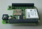
End Result
I wish I had a video of this first endeavour but unfortunately all I have is a photo I took. The bot here is a bit more advanced than what is described in this post (ie. ignore the ultrasonic transducer) but essentially it is simply the BBB mounted on top of the battery case, the micro motors stuck to the case with double sided tape and a ball caster. Broom broom.
Circuit Diagram and a Note on Power
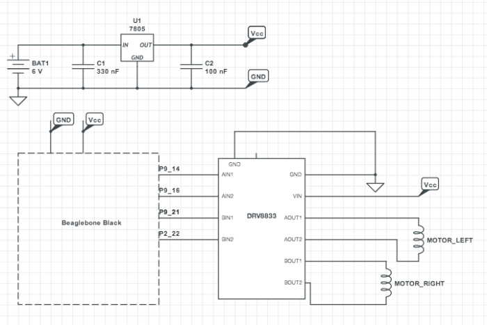
The BBB itself draws quite a lot of current, anywhere from 210-460mA on its own without any additional hardware like the motors. For initial work I powered everything off a bench supply (well, a wall-wart I found that did 5V at 700mA or similar) but dragging a cord around isn’t very robot-like, so I quickly put together a small regulator circuit to power it from batteries.
Technically the LM7805 requires 7.3V for a 5V output, at the moment I’m using 4 NiMH rechargeables (1.2V per cell) and a 1.5V AA, this gives 6.3V and it works just fine, even with the motors – I don’t know, maybe the LM7805 doesn’t do as good a job with less than 7.3V but it seems fine. As soon as I get upgrade the battery shell the robot sits on I’ll just migrate to 6 NiMH cells.

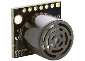 an amplifier and wave generator for them, along with interfacing them back into timers for distance measurement, but a package like the EZ1 takes care of all of this for you.