
 A differential drive robot’s two wheels are placed horizontally adjacent to each other, as if connected by an axle (their “axis”), and their speed is independently controllable. On most (all?) differential drive robots the axis running through the two wheels also runs through the centre of the bot so that any rotation occurs through its centroid in the x-y plane.
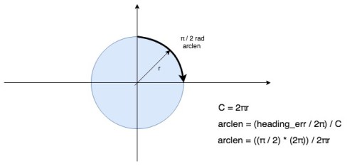
As mentioned in the previous post, there are times, such as when a significant correction in heading is required, when we want the robot to “spin on a dime”: that is, rotate around its centroid without changing its (x,y) position. This can be achieved using odometry. In order to rotate π / 2 rad (90 deg) each wheel must travel a distance of arclen, which is defined by the wheelbase (distance between the wheels) of the robot and the desired rotation angle. So, one implementation of rotation can simply be to rotate both wheels in opposite directions at the same speed and periodically (often) check their odometry readings: once they’ve travelled arclen the robot has rotated the required angle.
The problem with this approach is as mentioned in the previous post: the voltage/speed response curves of each motor are not identical. The Romi’s motor libraries accept a signed signed 16-bit integer (capped to -300 to +300) as input, which is converted into a PWM signal to the DRV8838 motor driver, which ultimately is represented as a control voltage to the motor. Instructing both motors to spin at “+100” will result in slightly different actual speeds in each motor. The net result is slip on one wheel (and/or drag on the other) and an invalidation of the assumption that because you’ve measured a distance travelled of d (via odometry) for one wheel that the arclen travelled was really d. In other words, you under or over rotate. While this seems theoretical, in practice it quickly manifests itself. Box test failed.
Luckily, the Romi’s control board has a built-in LSM6DS33 inertial measurement unit. This consists of 3-axis accelerometer and 3-axis gyroscope. Gyroscopes measure rotational motion (angular velocity), that is, how fast they (or the fixed body they’re attached to, in this case, oroboto) are rotating around a given axis. This angular velocity is measured in degrees per second. Just as we can measure (x,y) displacement by integrating translational velocity over time, we can measure angular displacement (rotation) by integrating angular velocity over time.
The course correction mode previously implemented with odometry becomes simpler:
- At t = 0 assume angle_rotated = 0
- Set speed of both motors to s
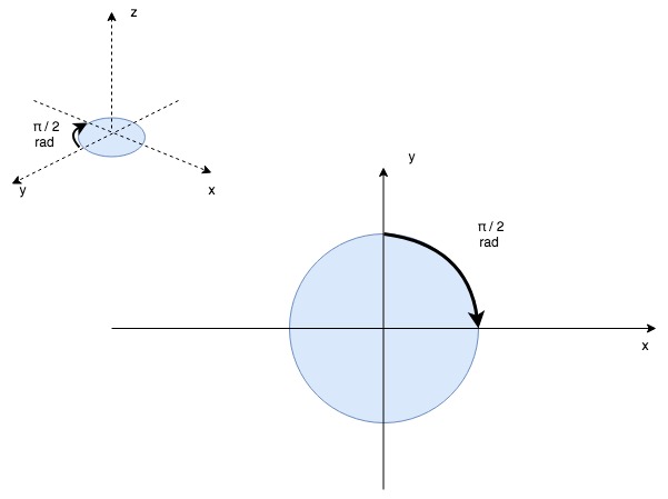
- Periodically measure (sample) angular velocity around the z-axis (the axis that runs through the center of the robot, “pinning” it to the floor: this corresponds to its change in heading (the interval of this periodic check is dt)
- Integrate the angular velocity with respect to dt, yielding angle_rotated (degrees rotated since t = 0)
- Stop when angle_rotated >= desired rotation
This is a simplification; in the code you can see the LSM6DS33 actually reports angular rotation in “gyrodigits” (digits per second, or DPS), which allow the device to support multiple levels of sensitivity / granularity and that it’s necessary to calibrate the gyroscope before use. Calibration allows some of the random noise the gyroscope experiences to be removed from each sample.
Each sample of the gyroscope’s angular velocity around an axis contains a random amount of noise (ie. some samples will under-report angular velocity, others will over-report angular velocity): continued integration of these samples accumulate that noise and result in drift: the integrated value (ie. the amount of rotation that has occurred since we started measuring) will become less accurate over time. Calibration helps to remove some of this noise but cannot account for all of it. If using the gyroscope to measure rotation over a long time period, this is a problem. Thankfully, course correction routines, where the robot is trying to correct for a specific amount of heading error, are short-lived and essentially “reset the drift clock” each time they start. At the start of the routine, we are seeking to correct for err degrees heading error from the current heading, which for the purposes of the correction, is considered “0 degrees”. The integration of angular velocity only has to occur until err degrees of rotation has occurred from that initial 0 degree starting point. Because this rotation occurs quickly (the robot can spin 360 degrees in under a few seconds, even when moving slowly) there isn’t time for drift to accumulate and as such the gyroscope is accurate under these conditions as illustrated in the videos below.
Drift becomes a problem when trying to use the gyroscope to measure rotational change over a longer time period. Consider a pilot who takes off along a runway with known heading (ie. perhaps it runs due north-south) and who has reset his gyroscope to “0 degrees” when facing north up the runway before takeoff. At this time, the gyroscope reading is accurate. After takeoff, his gyroscope is continually integrating angular velocity (in whichever axes it cares about, hopefully all three) with respect to that initial reset on the runway. Over time, a few hours into his trip, the gyroscope will have accumulated significant error through drift and will no longer be identifying accurate headings. A similar situation occurs with oroboto when using the gyroscope as an alternative to odometry when measuring change in heading between PID loop iterations. In this case the robot continues integrating gyroscope readings as it transits between waypoints, each time adding or subtracting from its last known heading. Over time, gyroscope drift causes these measurements to become less and less accurate and leading to incorrect heading adjustments for the PID loop. Box test failed.
As a method based on integration, odometry suffers exactly the same drift problems as the gyroscope, but in my testing, under the distances travelled (less than 100 meters), odometry was providing better accuracy than the gyroscope method.
One way to correct for drift is to combine the readings of a drift prone sensor (such as a gyroscope or wheel odometry) with the readings of a non-drift prone sensor, such as a magnetometer. This is called sensor fusion, a topic that deserves way more than one post alone.
Before delving into that rabbit hole, however, my next post will focus on interfacing the Romi to a Raspberry Pi I2C slave. This gives oroboto a huge amount of computing power to execute higher level navigational tasks and allows for simple robot-to-robot and robot-to-controller communication over WiFi.
